Setup menus are available in both Setup and Installer Setup. Setup allows only limited system settings, schedule programming, and other non-critical adjustments. Setup can be used by non-installers and operators.
Installer Setup offers four additional category menus of higher level programming. See Sections 3.2.4 Load Control, 3.2.5 Charger, 3.2.7 ReadyBlocks, and 3.2.8 External Source Control/ESC for full details.
NOTE:
The GenStar MPPT does not use universal default passwords and requires unique credentials to be created on first use. LiveView will prompt for an Administrative password the first time the webpage is loaded. The Lock/Unlock buttons will not be visible until a password is established.
MODBUS writes over Ethernet must be enabled to change any settings in LiveView. For security purposes, the, "MODBUS writes over Ethernet", enable/disable setting can only be modified on the local meter display.
Security related firmware updates will be provided for a minimum of five (5) years from date of manufacture.
Several Installer settings are originally chosen during commissioning, but changes to the installer settings can only be made in the Installer Setup menus. If no password is set in memory (factory default), then LiveView will prompt you to create one. Installer settings also include the six (6) basic setup topics described below.
3.2.1 - Date and Time (Setup and Installer Setup)
3.2.2 - Network Settings (Setup and Installer Setup)
3.2.3 - SD Card and Logger (Setup and Installer Setup)
3.2.4 - Load Control (Installer Setup)
3.2.5 - Charger (Installer Setup)
3.2.6 - Schedules (Setup and Installer Setup)
3.2.7 - ReadyBlocks (Installer Setup)
3.2.8 - External Source Control/ESC (Installer Setup)
3.2.9 - Meter Display (Setup and Installer Setup)
3.2.10 - Save and Load (Setup and Installer Setup)
Once all settings adjustments have been made for a given setup menu it must be saved before navigating to another setup menu or a different view. If any settings changes have been made in a setup menu without being saved, an "Abandon Changes" prompt will appear. Select Okay to save the new settings or select Cancel to abandon changes to leave the setup menu without saving.
When saving new settings, an EEPROM Settings Edit Fault may occur. Not all settings will cause this fault. After all settings have been modified, the EEPROM Settings Edit Fault can be cleared with a Reboot Control Command (See 4.6 Alarms and Faults and 4.8.4 System Commands).
3.2.1 Date and Time
(Setup and Installer Setup)
UTC (Universal Time Coordinated) is set at the factory. If the coin cell remains in place, UTC may not need adjustment. Conduct a web search for, "current UTC time", to confirm time is set correctly. Set the Date and Time in Installer Setup\Date and Time. The internal precision clock is used for log data time-stamping, ESC control, schedules, and other time-based functions. There are two options for keeping accurate time:
Internal clock uses the GenStar MPPT's built-in real-time clock. The coin cell battery allows Time and Date to be retained through power cycles. If using the internal clock, UTC time and date are entered, and an offset for local time zone is entered. Note that the local offset must be adjusted when a time zone changes to DST, and back.
Time server - if the GenStar MPPT is connected to the Internet, it has the ability to periodically update time and date from a time server(s). Go to Installer Setup\Network to specify up to three (3) time server addresses.
3.2.2 Network Settings
(Setup and Installer Setup)
If the GenStar MPPT is connected to a DHCP router, and the DHCP option is selected, network settings will automatically be assigned. If authorized, MODBUS Ethernet will show, "ENABLED".
Network Settings displays the current network settings configuration.
To change network settings remotely, first set the unit's on-board meter (Installer Setup) to allow remote writes over Ethernet. For security reasons, the, "MODBUS writes over Ethernet" enable/ disable setting can only be modified on the local meter display. This a safety feature to prevent unintended changes to custom settings, but it is not a replacement for proper network security. This feature does not block write commands on an EIA-485 network. Never connect units to an open or unprotected network.
Use the menus to configure.
MODBUS Settings
MODBUS and MODBUS TCP/IP are open standard protocols for communication between connected devices on serial and Ethernet networks respectively. The GenStar MPPT supports Modbus communication via serial (EIA-485/RS-232/USB ports) and Ethernet.
MODBUS ID and MODBUS IP Port - assign IDs as desired
All devices on a serial MODBUS network must have a unique MODBUS ID. All devices on an Ethernet MODBUS network must have a unique ID and common MODBUS IP port configuration.
Bridge Ethernet MODBUS TCP/IP requests with MODBUS Serial Messages
An Ethernet MODBUS TCP/IP message with a MODBUS ID that differs from the GenStar MPPT MODBUS ID will be, "bridged", and sent out as a serial MODBUS message on the GenStar MPPT's EIA-485, RS-232, and USB serial ports (see Figure 3 in Section 1.4). A response from a connected device on any of those serial networks will be packaged by the GenStar MPPT and sent as a MODBUS TCP/IP response back to the Ethernet network.
Wireless
Enable Wireless to turn on the Bluetooth® signal and use the Morningstar Mobile app.
TCP/IPv4
Adjust Ethernet connection parameters.
Time Servers
(Installer Setup Only)
If the GenStar MPPT is connected to the Internet, it has the ability to periodically synchronize time and date from a time server. There are three default, public NTP servers, which users can modify as necessary.
SNMP
(Installer Setup Only)
Edit SNMP Read Community (default: public) and SNMP Write Community Strings (default: private) [see section 5.6 for more information about SNMP].
3.2.3 SD Card and Logger
(Setup and Installer Setup)
The GenStar MPPT includes an SD Card for auxiliary data storage. The SD Card screen will display the SD Card Status and Total Storage. Choose one of the four options for data management: Format SD Card; Delete Log Data; Delete Settings File; or Delete Firmware File. The SD Card menu offers the following information and functions:
SUMMARY | |
|---|---|
Status | The SD card is detected-not detected |
Total Storage | Total addressable storage of the SD Card |
ACTIONS | |
|---|---|
Format SD Card | Format the SD Card (FAT32). WARNING: erases all contents on the card and creates system directories |
Delete Event Log Data | Delete event log data files from the /EVENTLOG directory only |
Delete Daily Log Data | Delete Daily Log Data files from the /DAILYLOG directory only |
Delete Settings File | Delete configuration setting files saved in the /SETTINGS directory |
Delete Firmware File | Delete firmware update file(s) in /FIRMWARE directory |
LOGGED DATA STORAGE
Use the Setup or Installer Setup Logged Data Storage drop-down to enable internal logging, or internal and SD Card logging.
There are three different loggers. The daily and hourly Loggers total and record important data once a day and hourly, respectively. The Event Logger records high-speed operational, network, and system-level information.
Choose to log data to the GenStar MPPT internal memory only or also allow log data storage on an SD Card. If the SD card is removed, the GenStar MPPT will continue logging to internal memory only. By selecting, "Internal and SD Card", and using an SD Card, the maximum amount of logged data will be substantially increased.
3.2.4 Load Control
(Installer Setup/Load)
The GenStar MPPT controller provides Load Control settings for the built in load controller. Selecting the Standard Button provides seven (7) different preset LVD/LVR load profiles (4 for lead acid batteries and 3 for Lithium batteries). See Table 9. GenStar MPPT Preset LVD-LVR (Load Control) Profiles in Section 4.3.
If a Standard preset LVD/LVR load profile is selected, the Copy to Custom button can be selected to start a custom profile using the selected preset values. When the Custom button is selected, the user has full flexibility to enter any desired load control values.
Custom settings can also provide State-of-charge (SOC) Load control settings options. These Low SOC Disconnect/Reconnect (LSOCD-LSOCR) settings will disconnect and reconnect the load based on battery SOC% (if available) for load control. The LSOC settings will only be enabled if SOC% is available from a ReadyShunt or a ReadyBMS.
Ready Shunt must be configured as a Net Branch Type Shunt (see section 3.2.7 ReadyBlocks)
ReadyBMS must be selected during commissioning with a supported battery (see section 2.6 Commissioning / Initial Configuration)
The following four (4) custom load control options are available to the right of the Custom button in LiveView:
Custom Load Control Options | |
|---|---|
Voltage Only | Enables LVD-LVR load control settings |
State-of-charge (SOC) ONLY | Enables LSOCD-LSOCR load control settings |
State-of-charge (SOC) and Voltage | Enables both LVD-LVR and LSOCD-LSOCR load control settings |
Always On | Load terminal voltage is never interrupted-disabled |
After setting State-of-charge (SOC) and Voltage, when either the battery voltage drops below LVD or SOC is below LSOCD, the disconnect process (including LVD/LSOCD warning) will begin. After an LVD or LSOCD has disconnected the load, the load will not be reconnected again until both the battery voltage is above LVR and SOC is above LSOCR.
Load Current Compensation settings are available with the LVD-LVR settings only. LVD/LSOCD Warning Time settings are applied to both the LVD-LVR and LSOCD-LSOCR settings and will provide a notification before disconnecting the load. Load High Voltage Disconnect and Reconnect (HVD-HVR) settings can be used to protect voltage sensitive loads. See Section 4.3 for more information about Load Current Compensation, LVD/LSOCD Warning Time and HVD-HVR settings.
CAUTION:
Due to the possibility of SOC inaccuracies, SOC ONLY settings may be risky. It is recommended to use SOC and Voltage settings so there is a backup LVD setting to ensure that the battery is not over discharged.
3.2.5 Charger
(Installer Setup)
Also refer to LiveView or meter map for all custom settings options.
Solar Input Mode | |
|---|---|
MPPT (default) | Allow the controller to use its TrakStar Maximum Power Point Tracking algorithm to determine the optimal solar array voltage operating point. |
Fixed Vmp | Disables the MPPT algorithm and uses the Specified value as a static source voltage operating point. |
Voltage to %VOC | Disables the MPPT algorithm and instead uses a percentage of measured input source open-circuit voltage as the static voltage operating point. Open-circuit voltage (Voc) of the input source is measured by the controller periodically. |
Battery Bank Definitions | |
Battery size in Amp-hours | Battery bank Ah capacity is always required when using the ReadyShunt with a Net shunt or BMS Block to measure the battery SOC and vital for system informational purposes. |
Battery SOC Efficiency | Is a required setting when using the ReadyShunt with a Net shunt to measure the battery bank SOC. Efficiency settings are set for one-way efficiency. Lead Acid (9.4%) and Lithium (99%) presets or custom settings are available. |
Battery Current Limit | If enabled, the control will limit its net charge current into the battery (GenStar net current or Net Shunt battery current if present) to the given limit. If disabled, the control will contribute up to its maximum rated current. |
Battery Current Limit Requires Shunt | Requires a ReadyShunt with Net shunt to measure battery current. Used to limit battery current when there are external charging sources. |
Closed-loop BMS | Enabled when commissioned with a BMS Block for closed-loop battery management |
RTS Required | Enabled or disabled during commissioning to require an RTS for temperature compensation to operate. |
If Battery Current Limit Requires Shunt or RTS Required is disabled, it does not disable current limiting based on a Net Shunt or temperature compensation with an RTS. It just won't cause a fault if not present.
Battery Charge Settings
WARNING: EQUIPMENT DAMAGE
Improper battery charge settings can severely damage batteries. Take great care when applying any charging settings.
See Section 4.2 for descriptions of many charging settings, and, "Installer Setup", below, for additional variable descriptions.
Define the charging parameters for the battery. Choose a standard charging preset from a range of batteries, OR enter a custom profile if needed.
Copy to Custom
Copies the values in the Standard Profile column to the Custom Profile column. Use this feature to start with a standard charging profile that is close to the desired configuration, copy to custom, and then edit the values for a specific charging application.
Preset options are described in Section 4.2.2. Refer to the battery manufacturer's documentation for guidance.
For more standard settings information, and further custom settings adjustment, expand the Installer Setup bar at the bottom of the section.
Battery State-of-Charge (SOC) LED Transitions
(also see SOC measurements in Section 3.2.7)
The battery SOC LED transitions will be based on the selected criterion - an estimation based on battery voltage or SOC percentage in the case of ReadyBMS or ReadyShunt applications.
Enter the battery SOC LED transition voltages or SOC percentages that correspond with the desired
LED color or color combination for that voltage or SOC percentage. When there is no SOC percentage value available from a ReadyBMS or a ReadyShunt, the LEDs will display an estimated state-of-charge (SOC) based on the battery voltage.
INSTALLER SETUP SETTINGS
Maximum Regulation Voltage
Sets the absolute maximum battery voltage limit. The charger will not charge above this value regardless of charge stage target voltage or temperature compensation effects. Note that the default Max Regulation Voltage setting is disabled for all presets.
Maximum Equalization Current Limit
Sets an absolute limit on the amount of Equalization Stage charging current.
Battery High Voltage Disconnect-Reconnect (HVD-HVR)
Set voltages at which charging current ceases (HVD) and then resumes (HVR)
Temperature Compensation Coefficient (mV/°C)
Set to adjust the charging set-point to optimize charging for different battery temperatures
Minimum Temperature Compensation Limit
Set the lowest temperature at which temperature compensation will occur. Temperature compensation will not occur below this temperature.
Maximum Temperature Compensation Limit
Set the highest temperature at which temperature compensation will occur. Temperature compensation will not occur above this temperature.
Low-Temperature Current Foldback (0%, 100%) - low and high temperature settings
Protects lithium batteries from being charged in cold conditions by defining the bounds of charge current reduction due to low battery temperatures. Configuration can be done in either LiveView or the meter display interface, using an Installer Setup Password. If no password is set in memory (factory default), then LiveView will prompt you to create one.
The low temperature-0% limit defines the temperature at which the controller will stop providing battery charging current. The high temperature-100% limit defines the lowest temperature at which the controller will deliver 100% of the controller's rated output charging current. Charging current is tapered linearly from 100-0% between high and low temperature settings
High-Temperature Current Foldback (100%, 0%) - low and high temperature settings
Defines the bounds of charge current reduction due to high battery temperatures. Using the Installer Setup password, configuration can be done in either LiveView or the meter display interface using an Installer Setup Password. If no password is set in memory (factory default), then LiveView will prompt you to create one.
The high temperature-0% limit defines the temperature at which the controller will stop providing battery charging current. The low temperature-100% limit defines the highest temperature at which the controller will deliver 100% of the controller's rated output charging current. Charging current is tapered linearly from 100-0% between low and high temperature settings
Absorption End - Amps
Set a net current threshold below which the controller will transition from the Absorption to the Float Stage - see Absorption End Amps Time below.
Absorption End - Amps, Time
Set the time required below Absorption End Amps threshold for the controller to transition from the Absorption to the Float Stage.
3.2.6 Schedules
(Setup and Installer Setup)
Use the Schedules Page to define schedules for ReadyRelay functions. The following ReadyRelay functions can be scheduled and require one of the following relay assignments in ReadyBlock configuration (see Section 3.2.7).
External Source Control (ESC)
Command/Schedule
For Relay-ESC scheduling, the Schedules Page Menu sets only the Relay-ESC timing for when each of the Custom ESC Start-Stop conditions take effect (see Section 3.2.8). ESC schedules can be set in the ESC Custom Settings menus or in the Schedules menu. Command/Schedule relays can be scheduled in the Schedules menu only.
3.2.7 ReadyBlocksTM and ReadyShunt SOC Measurements
(Installer Setup)
ReadyBlock Configuration
Installed blocks will populate the ReadyBlock Configuration Box in the LiveView webpage. The ReadyShunt can also be configured in the local display meter. The location of each block is indicated by positions 1-3, relay A or B for each Relay Block, and shunt A or B for each Shunt Block. Position 1 is the left-most block.
Relay A is on the left, and relay B is on the right. Shunt A uses the upper-tier terminals, and Shunt B uses the lower-tier terminals. Choose a block to configure. See ReadyRelay, ReadyShunt and ReadyBMS instructions below.
ReadyRelay (RB-Relay)
The ReadyRelay is an expansion block that adds AC and DC-rated relay dry contact hardware functionality and firmware control and logic to the Morningstar GenStar MPPT charge controller. The ReadyRelay can be used to provide additional load control, external charging source control and other signaling functionality.
Relay Function
Choose how a relay will function: Threshold; Faults and Alarms; Charge Stage; External Source Control (ESC) Start-Stop; Command/Schedule. Each of the two Relay Block relays can be configured for a unique function:
Threshold - no scheduling. Choose whether the threshold will be reached from a rising (lower) or a falling (higher) value, relative to the threshold; choose a variable, and then enter the desired ON and OFF thresholds, along with desired delays. Activate ReadyRelays using Command buttons (after configuration in LiveView Installer Setup\ ReadyBlock\Relay assignment).
Faults/Alarms - no scheduling. Programming will activate a relay to control optional devices based on specifically occurring fault conditions:
When charging has stopped due to a fault
When charging has stopped due to high battery voltage
When Load has disconnected due to a fault
When the load has been disconnected due to high battery voltage
An over-temperature alarm has occurred
Charging current is being limited
Charging Stage - no scheduling. Toggles the relay for use with optional devices when the selected charge period - Bulk, Absorption, Float, Equalization, Night - is active. Optionally, relay start and exit delays can be set.
External Source Control (ESC) Start-Stop. A) Assign a relay to, "ESC Start-Stop" signal. B) Save and proceed to LiveView\Installer Setup\ESC setup and program accordingly for Manual or Custom. Manual provides ON-OFF Commands only. Custom provides conditional automated start-stop with schedule control options. See Section 3.2.8 External Source Control (ESC). Also see Section 4.8.5 - ESC Commands.
To enable the use of the Manual or Automatic Source Control Profiles, an External Source Control (ESC) control signal must be assigned to a relay (block) - see Section 3.2.8 on ESC.
Command/Schedule. Provides ON-OFF Scheduling with manual ON-OFF Commands. Only relays that have been configured for "Command/Schedule" function can be controlled by, " ReadyBlock", Relay Commands.
Proper generator/auxiliary equipment relay wiring is required - see ReadyRelay manual for terminal connections diagram.
ReadyShunt (RB-Shunt)
The ReadyShunt is an expansion block designed measure and display net current flow into the battery, or to measure and display source or load auxiliary current.
Battery state-of-charge (SOC) reporting
Viewable in the, "LiveView", tab of the LiveView program, under "Battery Summary"
A ReadyShunt block and external shunt(s) can be used to monitor SOC for reporting, and can enable SOC based load control (see Section 3.2.4 - Load Control - above). When a ReadyBMS is configured during commissioning, it governs all aspects of charging and state-of-charge (SOC) reporting - even with a ReadyShunt installed. Without a ReadyBMS, an installed NET shunt at the battery and a ReadyShunt Block assignment in Installer Setup can enable an SOC sub-system with specific operating parameters - see "Shunt Block Net Shunt Configuration" below for details.
For ReadyShunt installation procedures, refer to the ReadyShunt manual at:
morningstarcorp.com\support library
For Shunt Block Configuration for SOC see ReadyShunt manual p. 16, Figure 5-3 for wiring diagram.
After a ReadyShunt is installed:
Always make sure to update the Firmware to the latest version available (see Section 4.10 Firmware Updates)
Access the GenStar unit by opening a LiveView web page - see Section 3.1.3.
Go to Installer Setup\ ReadyBlocks, and choose the desired Shunt Block.
Enter "SOC" for the name.
Enter the external shunt full-scale Millivolt and Amp ratings.
Assign the branch type as "NET". Note that a branch type change will cause a fault, and a system re-boot is required.
DEFINITIONS
Currently, voltage and current setpoints, and full SOC duration time are only configurable via Modbus register value assignment. After any changes to SOC-related value assignments, the controller must be re-booted.
Battery Current
The net battery charging current; the charging current that is measured by the NET battery shunt.
Current Setpoint
The assigned current value that indicates 100% SOC. If an Absorption End-Amps setting is made in Battery Charging Setup, it must be less than or equal to the Current Setpoint - otherwise, full SOC will not be reported.
CALCULATION: A default of 2% of battery capacity (A-h) equals the current setpoint in Amps. Also see Condition #2 below. Battery capacity is entered in Installer Setup\Charger\Battery Info.
Voltage Setpoint
The calculated voltage, based on programmed Absorption voltage, that when exceeded by actual battery voltage, is an indicator of 100% SOC - see Condition #1 below.
Full SOC Determination
The battery SOC will be reported at 100% when the two conditions below are true, and after a default cumulative duration of five minutes is reached.
Condition 1: (based on calculated SOC Voltage Setpoint): Battery voltage is greater than or equal to the Voltage Setpoint
Condition 2: (based on calculated SOC Current Setpoint): Battery current is less than or equal to the Current Setpoint
Partial SOC Determination
Once full charge has been verified, the GenStar algorithm can then calculate a subsequent existing charge level, and use full capacity to express SOC as a percentage.
SOC Programming Applications
SOC LED percentage threshold variables - select SOC percentages to be used for battery SOC LED transitions - see Default Battery SOC LED Percentages Table in Section 4.5 Battery State-of-Charge (SOC) LED Transitions.
Load disconnect-reconnect thresholds - using LiveView, load disconnect and reconnect can be programmed based on a state-of-charge percentage - see Section 3.2.4 Load Control.
Variable for ReadyRelay threshold - an SOC percentage can be used as a variable assigned to trigger a relay for ON-OFF threshold settings.
Variable for ReadyRelay ESC - an SOC percentage can be used as a variable assigned as a Start or Stop condition for an external source input to the battery bank.
ReadyBMS (RB-BMS)
The BMS Block can also interface with lithium batteries for, "closed loop", charging control and data reporting. Closed loop communication and integration is developed and tested in tandem between Morningstar and a limited number of lithium battery manufacturers including the following:
Deka (duration)
Discover Advanced Energy (AES)
Pylon Technologies Co., Ltd. (PylonTech)
WeCo S.r.l.
See the Energy Storage PartnerTM program (ESP) webpage for BMS Closed Loop Setup Guides for the manufacturers listed above. BMS Closed Loop Setup Guides will be available for additional manufacturers on the ESP webpage as they become available.
https://www.morningstarcorp.com/energy-storage-partner-program/
BMS closed loop integration must be enabled during commissioning by selecting YES when prompted for "BMS Block?" and selecting the battery model from the dropdown list (see Section 2.6 Commissioning / Initial Configuration).
3.2.8 External Source Control (ESC)
(Installer Setup)
To enable the use of the Manual or Automatic Source Control Profiles, a ReadyRelay must be programmed for ESC Start/Stop as seen in Section 3.2.7 Relay Function #4. As of this publication, only one ESC profile can be set up for the system. If multiple relays are set up for ESC Start/Stop they will all share the same ESC settings.
INTRODUCTION
The ReadyRelay can be used for manual or automated on/off control of external charging sources. The GenStar External Source Control (ESC) settings provide basic and advanced on/off control for an external charging source. ESC is used for hybrid off-grid solar PV systems that have a backup generator or fuel cell and can also be used for grid connected solar backup systems.
With hybrid off-grid solar PV systems, the ESC typically remains off/ disconnected while system loads are powered by the battery and solar PV array. When the Solar production is unable to keep up with the load usage, the ESC can be called on to recharge the battery as needed. With grid backup systems, the ESC (grid) might be set up to remain on much of the time and be disconnected during the day to power the load from the battery and solar PV array.
ESC SETUP OVERVIEW
Set a ReadyRelay for ESC Start/Stop
Set ESC Timing Controls
Set an ESC Mode (Manual or Custom)
If using Custom for automated Start - Stop control
Select desired Control Criteria option(s) (at least one Emergency or Start Charging)
For each Control Criteria option, set ESC Control Conditions (if needed)
Set ESC Schedule(s)
ESC PROGRAMMING
Opening ESC Screen:
The ESC LiveView screen displays ReadyRelay assignment(s) at the top. Below that are the following two drop-down menus.
ESC Timing Controls: provides minimum and maximum runtime and minimum offtime for the external source.
ESC Modes: determines the conditions that will trigger start and stop control of the ESC relay in addition to weekly schedules when each condition is active.
All of the ESC Timing Controls and Modes are disabled by default.
ESC TIMING CONTROLS
The ESC Timing Control settings can be programmed to allow the external charging source to operate for a sufficient amount of time (Minimum Run Time), prevent it from operating for too long (Maximum Run Time) or prevent it from being started again too soon after shutting off (Minimum Off Time).
Minimum Run Time: Sets the least duration the external source can operate. Maximum Run Time: Sets the greatest duration the external source can operate.
Minimum Off Time: Sets a requirement of time elapsed from turning off before the external source can start again.
ESC Timing settings are disabled by default. To prevent the possibility of the ESC Run Time being too short or too long, or from starting again too soon, ESC Timing settings are recommended.
Timing Controls always remain in effect and will always delay or interrupt (not disable) all types of ESC controls until the minimum or maximum timing condition has been met. This includes all control initiated by ESC Custom Mode settings, even "Emergency Charging" and "Prohibit Operation" (see Modes Setup - Custom), in addition to all ESC Enable and Disable Commands. The only exception is the ESC E-Stop Command that will ignore the Minimum Run Time setting. See Section 4.8.5 External Source Control (ESC) Commands.
Therefore, it is important that the Timing Control settings are set correctly. For example, the Maximum Run Time should not be set for less than the longest desired amount of runtime for the charging source.
(Intervals are met when elapsed time equals required time)
An example of ESC Timing Controls are displayed in the graph in Figure 11 below.
EXTERNAL SOURCE CONTROLS TIMING SEQUENCE EXAMPLE
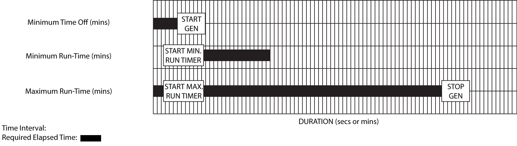
Figure 11. External Source Control Timing
ESC MODES SETUP SCREENS
The drop-down menu provides options for Disabled, Manual or Custom Profiles:
DISABLED
External Source Control function is disabled
MANUAL
External Source start/stop control can be triggered manually via an "ESC" Command or Soft-key. Use LiveView ESC Commands, display-meter commands or Softkey (see Sections 3.1.1 and 3.2.9) to start or stop an external source manually. Note that Manual ESC Enable and Disable commands will not override ESC Timing controls.
CUSTOM
External Source Control can be triggered automatically using Custom ESC settings for an ESC Start- Stop assigned relay. When Custom Mode is chosen, a Custom ESC setup screen with four (4) Control criteria options will appear below on the left.
Start Charging: Set Start, Stop and Schedule criteria for ESC (can be prohibited or paused)
Emergency Charging: Set Start, Stop and Schedule criteria for ESC (Always active - no schedule settings, can be prohibited, cannot be paused)
Pause Charging: Set Pause, Resume and Schedule criteria to pause and resume charging (overrides Start Charging settings only)
Prohibit Operation: Set Schedule (no other criteria/conditions) when ESC charging is prohibited (overrides Start Charging and Emergency Charging)
There is also a "use factory defaults" option on the right. The factory defaults include an Emergency Charging (Avoid LVD) preset and a Start Charging (Low Battery / Bulk) preset.
After selecting a scheduling-control option, select from a drop-down list of presets or "use custom settings". Note that all presets can be modified after they are selected.
Multiple ESC Controls
Multiple ESC Control criteria options can be programmed at the same time, each with its own ESC settings and schedule. After selecting from Emergency Charging, Start Charging (1, 2, and 3), Pause Charging, or Prohibit Charging, the corresponding Custom ESC Card will be displayed.
At least one Emergency Charging or Start Charging custom setting must be used to enable (Start) ESC charging. The only difference between Emergency Charging settings options and Start Charging settings options are the presets.
Prohibit Operation will always override all Emergency Charging and Start Charging operation and Pause Charging will only override ESC Start Charging operation, but not Emergency Charging operation.
Typically the Start Charging settings are programmed so they will start ESC operation before the Emergency Charging settings. In this way, the Emergency charging settings act as a backup to the Start Charging settings, and remain active when the Start Charging operation is paused or not scheduled.
ESC Control Conditions
Start and Stop Control Conditions are set in the Start Charging and Emergency Charging ESC Cards. Pause and Resume Control Conditions are set in the Pause Charging ESC Card. ESC Control Conditions are not available for Prohibit Charging.
The factory defaults and presets include ESC Control Conditions settings. These settings can be modified by selecting the wrench icon. Alternatively, Custom ESC Control Condition settings can be selected and set.
The following applies to Pause and Resume Control Conditions also.
ESC Start and Stop Charging Control Conditions will be paired for each ESC Card only. Only the paired Stop Conditions or end of the Schedule will deactivate the ESC Start Charging condition once it has been started.
Set the Start charging conditions so that the charging is only started when charging is needed and not started when it is not needed. Set the paired Stop charging conditions so it is coordinated with the Start Charging Conditions to meet a specific amount of charging after it has been started.
When setting custom ESC Control Conditions, it must always include both a Start charging setting and a Stop Charging setting.
Each ESC Control Condition (for Start, Stop, Pause or Resume) can be set with up to .4 different conditions and combined logically with "any" (OR) or "all" (AND). Two or more Conditions can be combined with "any" or "all" into a group. Once there are two conditions in a group, a second group of Condition(s) can be formed.

Once set, a summary of the Start, Stop, Pause or Resume conditions will be displayed in the ESC Card describing the control conditions.
For Example: "Start charging when Battery Voltage is less than 23.4V for 5 minutes OR LVD Warning occurs for 1 minute."
ESC Schedules
(Schedules entered in Custom ESC Setup OR Installer\Schedules)
Each Custom ESC Card includes Schedule Settings on the right. Each of the ESC Schedules can also be set in the Schedules Setup menu (Section 3.2.6 Schedule).
By specifying various schedules, a broad schedule structure can be achieved. If there are no ESC Control criteria set, the ESC Control will operate according to a Schedule only. If ESC Control Conditions is set, the ESC Schedule determines when Start Charging (1, 2, and 3) or Pause Charging operations are active. Emergency Control Conditions are always active with no schedule settings.
ESC Control operation will not start before, or extend beyond the ESC schedule. For example, if Charging starts 1 minute before the Schedule ends the charging will also stop, unless overridden by Minimum Run Time.
Types of Control Conditions
Four different types of conditions can be used: Simple Condition, Variable Comparison, Range Condition, Event.
Different types of conditions | |
|---|---|
Simple condition | Select a Variable, Threshold value and Delay Time. Example: Stop Charging 1: when Battery Voltage > 26.4 V for 1 hour |
Variable comparison (may not have a viable use) | Select two different Variables for relational comparison (< or >) and a Delay Time |
Range condition | Select a Variable, upper and lower values for the Range and Delay Time. |
Event | Select a type of Event and Delay Time Example: Start Emergency Charging: when LVD Warning occurs for 1 minute |
The Time Delay settings can provide some certainty that conditions are not just temporary, and will not, "falsely", trigger the control. Another reason to use the delay might be to allow a certain amount of charging time after reaching a Stop condition.
To prevent overcharging of the battery or unintended run-time of the charging source, ESC Stop Condition Settings should be considered very carefully. For example, if an Event Stop setting is set to Stop charging when Charge Stage Absorption occurs, it will only be triggered after the GenStar solar controller has reached the Absorption Charge Stage and will not be triggered during Bulk, Night or Solar Controller Fault.
Table 5 provides all of the ESC Control Condition Presets available for the GenStar MPPT controller. The battery voltages in the table are for a 12V Nominal system (multiply by 2 for 24V or by 4 for 48V).
Factory Defaults | Start Condition | Stop Condition |
Emergency Charging Start Charging 1 | LVD occurs for 1 min Battery Voltage ≤ 11.8V for 5 min | Battery Voltage ≥ 12.1V for 1 hour Battery Voltage ≥ 13.3V for 1 hour |
Start Charging (1,2,3) | Start Condition | Stop Condition |
On a Schedule | On Schedule (can add) | On Schedule (can add) |
Low battery / Bulk | Battery Voltage ≤ 11.7V for 5 min | Battery Voltage ≥ 13.3V for 1 hour |
Low SOC / Bulk | Battery SOC ≤ 20% for 5 min | Battery SOC ≥ 75% for 1 hour |
Large DC Load / Reduced DC Load | Net Battery Current < -20 A for 30 min | Net Battery Current ≥ -10A for 10 min |
Emergency Charging | Start Condition | Stop Condition |
Avoid LVD | LVD occurs for 1 min | Battery Voltage c≥ 12.1V for 1 hour |
Low Battery Voltage | Battery Voltage ≤ 11.5V for 1 min | Battery Voltage ≥ 13.1V for 1 hour |
Pause Charging | Pause Condition | Resume Condition |
On a Schedule | On Schedule (can add) | On Schedule (can add) |
Prohibit Charging | No Conditions allowed | No Conditions allowed |
On a Schedule | N/A | N/A |
Table 5. ESC Control Conditions Presets (12V Nominal - Schedules not shown).
3.2.9 Meter Display
(Setup and Installer Setup)
The Meter Display settings include the following Settings Tabs.
Language: (English, Espanol, Deutsche, Francais) and Temperature (Celsius, Fahrenheit)
Screen Settings: Backlight Timer, Brightness, Contrast
Main Displays: Auto-Scroll and Auto Return
Map Soft-key Commands: Momentary Press and Press and Hold -- hold time is >2 seconds
3.2.10 Save and Load
(Setup and Installer Setup)
The GenStar System Settings can be saved as a system image configuration file to the GenStar SD card with LiveView or the meter display - Setup\Save & Load. To Save settings enter a filename and select Save (the filename can have up to 8 characters). Load settings from the SD Card by choosing a file and then clicking on the Load button. After loading the settings to the controller, review and verify the Settings in the Setup menu or in the individual setup menus.
When loading a system image configuration from an SD Card, ensure that the destination device has been commissioned for the same system voltage, battery profile, and RTS; otherwise, there is a potential risk of system damage or bodily injury.