GenStar MPPT exterior features are shown in Figure 3. A brief description of each feature follows the figure.
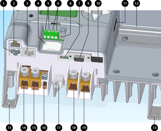
Figure 3. GenStar MPPT Interior Features.
Interior Features | ||
|---|---|---|
1 / 2 | MS-CAN In and Out Ports | Proprietary Morningstar device communication protocol ports |
3 | Ethernet Port | RJ-45 socket for LAN/Internet connection |
4 | Coin Cell (CR-2032) | Back-up battery for the real-time clock |
5 | Battery Voltage Sense Terminals | Terminals for battery voltage input provide accurate battery voltage measurement |
6 | Remote Temperature Sensor Terminals | Connection points for a Morningstar RTS to remotely monitor battery temperature |
7 | USB-C Port | USB-C data / Modbus port |
8 | Positive Load Terminal Lug | Positive connection point for loads |
9 | Serial RS-232 Port | 9-pin serial connector (female DB9) |
10 | EIA-485 Port | 3-terminal connection for serial 485 networks (removable plug connector) |
11 | ReadyRail Connection | 20-PIN female ReadyRail connection interface for ReadyBlocks |
12 | ReadyRail | Standard 35mm DIN mounting plate for mounting snap-in ReadyBlocks |
13 | Lower Mounting Screw Holes (2) | Used to secure lower part of GenStar MPPT to the wall |
14 / 15 | Battery/PV Common Negative Terminal | Connection points for battery or PV (-) power cable |
16 | Negative Load Terminal Lug | Negative connection point for loads |
17 | Equipment Grounding Terminal Lug | Chassis grounding point for system equipment |
18 | PV Positive Terminal Lug | Connection point for PV positive cable |
19 | Battery Positive Terminal Lug | Connection point for battery positive cable |