WARNING: FIRE HAZARD
If multiple units are used in parallel for more charging current, the battery conductor wiring must be sized for the total sum of all the current ratings of the combined controllers.
CAUTION:
U.S. installed wiring must conform to all current U.S. NEC, ANSI/NFPA 70 requirements, and to any local regulations. Non-U.S. installations must meet all national and local requirements of the country of installation.
Before connecting any wires, read the instructions in this entire section, and lay out the lengths and routes needed.
When wiring, secure and contain wire runs as required by code.
Three (3) ferrite chokes are included for individual installations around an RTS cable, PV (+) and (-) cables (in one choke) and an Ethernet cable. See Figures 6 and 7 for installation details conforming to FCC Class B EMI requirements. Each core must be installed as close to the GenStar MPPT as possible.
Proper wire type and size is required for all installations. Use only UL-listed Class B or Class C stranded wire rated for 300 Volts and 75°C or higher.
Copper wire is recommended instead of aluminum due to its ease of use, superior conductivity, strength and thermal expansion properties.
Battery and PV input terminal sizes | 8 - 1/0 AWG (10 - 53.5mm2) |
Load terminal wire sizes | 1.4 - 6 AWG (2.5 - 13.3mm2) |
Conductor ampacity (current carrying capacity) must be greater than the maximum current expected in the power circuits.
Accepted practice for system design requires that DC conductors are sufficiently sized to limit voltage drop losses to 2% or less. The table in Appendix C provides wire sizing information and distances for required maximum 2% voltage drop in GenStar MPPT wiring applications.
Also see Appendix C, "Wire Sizing", for copper wire sizing instructions, including minimum wire sizing requirements.
For Accessory Wiring, refer to schematic in Figure 6 below when following 2.5.1 and 2.5.2 on next pages.
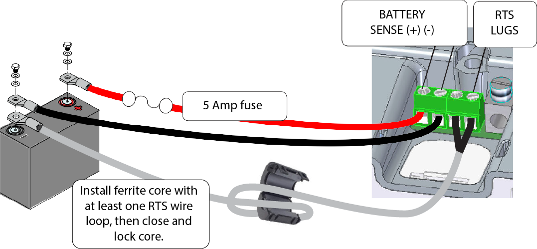
Figure 6. Accessory Installation Detail.
2.5.1 Battery Voltage Sense Wires
Refer to Figure 6.
When connecting Battery Sense Wires, install a 5 Amp fuse in the (+) sense wire, within six inches (150 mm) of the (+) battery terminal.
Due to connection and cable resistance, voltage drops are unavoidable in all power cables that carry current (See Figure 6). If Battery Sense wires are not used, the controller must use the voltage reading at the battery power terminals for regulation. This voltage may differ from the actual battery bank voltage due to voltage drop.
Battery Voltage Sense is a high impedance connection that enables the GenStar MPPT to measure the battery terminal voltage precisely with small gauge wires that have no voltage drop. When connected directly to the battery, the sense wires will improve battery charging accuracy. Battery voltage sense wires are recommended, but may not be necessary when using larger battery cables and/or shorter battery wire lengths.
Generally accepted wiring practice is to limit voltage drops between the charger and the battery to 2%. Even properly sized wiring with 2% drop can result in a 0.3 volt drop for 14.4V charging. Voltage drops will cause some undercharging of the battery.
The controller will begin Absorption or limit equalization at a lower battery voltage because the controller measures a higher voltage at the controller's terminals than is the actual battery voltage. For example, when the Absorption Target Voltage is 14.4V, if there is a 0.3 volt drop between the controller and battery, the controller will sense 14.4V at its battery terminals when the battery voltage is only 14.1V. This will make the controller enter Absorption stage too prematurely.
Note that the battery sense wires will not power the controller, and the sense wires will not compensate for losses in the power wires between the controller and the battery. The battery sense wires are used to improve the accuracy of the battery charging.
The two sense wires can range in size from 1.0 to 0.25 mm2 (16 to 2.4 AWG), and should be cut to length as required to connect the battery to the voltage sense terminals. The two-position terminal - to the left of the Load (+) terminal (beyond the RTS terminals) (see Figures 6 and 7) is used for the battery sense connections. A twisted pair cable is recommended but not required. Use UL rated 300 Volt conductors. The voltage sense wires may be pulled through conduit with the power conductors.
After observing correct polarity, connect both battery voltage sense wires to the GenStar MPPT at the two-position Battery Sense terminal, and to battery (+) and (-) terminals. No damage will occur if the polarity is reversed, but the controller cannot read a reversed sense voltage.
Tighten the connector screws to 5 in-lb (0.56 Nm) of torque.
The maximum length allowed for each battery voltage sense wire is 98 ft (30 m). Connecting the voltage sense wires to the RTS terminal will cause an alarm.
NOTE:
If the battery input voltage is greater than 5 Volts different from the Battery Sense, due to voltage drops
or faulty connections, the Battery Sense input will not be recognized by the GenStar MPPT. An alarm will be set until the condition has been corrected
Although not required to operate the GenStar MPPT controller, a battery voltage sense connection is recommended for best performance.
2.5.2 Remote Temperature Sensor With Ferrite Choke
Refer to Figure 6.
To enable temperature compensation settings (mV/ °C) which are required for Lead-acid batteries, an RTS must be used. Otherwise, charging will be based on a temperature of 25°C. Use of an RTS is strongly recommended.
An RTS can be added at any time during system installation (refer to Figure 6).
All lead-acid battery charging settings are based on 25°C (77°F). The GenStar MPPT default Lead- acid battery temperature compensation presets are -30mV/ °C @ 12V. This means that if the battery temperature varies by just 5°C, the charging target regulation voltage should change by 0.15 Volts for a 12 Volt battery.
This is a substantial change in battery charging, so it is important to always use the included Remote Temperature Sensor (RTS) with lead-acid batteries.
Lithium batteries do not require temperature compensation. Therefore, temperature compensation is disabled for all of the GenStar MPPT lithium battery presets. However, if the lithium battery temperature drops below freezing or becomes very hot during charging, it can cause irreversible harm to the battery. Therefore, where the battery temperature can get excessively low or high, it is important to use the low or high temperature foldback settings together with an RTS. During these conditions, the foldbacks will allow charging to taper off or become disabled. All of the GenStar lithium battery presets include low temperature foldback settings. See Configuration Section 3.2.5 for details on foldback settings.
The RTS must be used to enable low and high temp foldback settings which are often used with
lithium batteries.
Never place the temperature sensor inside a battery cell. Both the RTS and the battery will be damaged.
The RTS cable may be shortened if the full length is not needed. if a length of cable is removed, be sure to re-install the ferrite choke on the RTS cable as close as possible to the controller. This choke ensures compliance with electromagnetic emissions standards.
INSTALLATION
Connect the RTS to the two-position terminal located immediately to the left of the Load (+) terminal (see Figures 6 and 7).
The RTS is supplied with 33 ft (10 m) of 22 AWG (0.3.4 mm2) cable. There is no polarity, so either wire (+ or -) can be connected to either screw terminal. The RTS cable may be pulled through conduit along with the power wires. Tighten the connector screws to 5 in-lb (0.56 Nm) of torque. Separate installation instructions are provided inside the RTS bag.
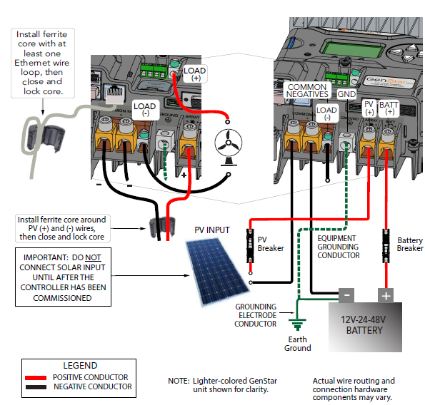
Figure 7. GenStar MPPT Power Wiring.
2.5.3 Grounding and Ground Fault Interruption
Refer to Figure 7.
For safety and effective lightning protection, it is recommended and may be required by code, that the negative conductor of the charging system be properly grounded (See Figure 7). Do not connect the negative system wire to the case grounding terminal. The GenStar MPPT does not have internal ground fault protection; but where the NEC requires the use of a ground fault protection device (GFPD), the system electrical negative must be bonded through a GFPD to earth ground at only one point.
SYSTEM GROUNDING
The DC system should be bonded to ground with a connection to the primary battery circuit. It can be bonded to ground directly or through an AC service panel if there is an inverter installed in the system. For the DC system grounding electrode conductor (GEC) sizing requirements, refer to NEC Section 250.166, or applicable local regulations or code.
This unit is not provided with a GFDI device. This charge controller must be used with an external
GFDI device as required by the Article 690 of the National Electrical Code for the installation location.
When a ground fault is indicated, battery terminals and connected circuits might be ungrounded and hazardous.
NO POWER OR ACCESSORY TERMINALS ARE ELECTRICALLY ISOLATED FROM DC INPUT, AND MAY BE ENERGIZED WITH HAZARDOUS SOLAR VOLTAGE. UNDER CERTAIN FAULT CONDITIONS, BATTERY COULD BECOME OVER-CHARGED. TEST BETWEEN ALL TERMINALS AND GROUND BEFORE TOUCHING.
Follow local electrical installation code and use green/yellow, green or transparent insulated grounding-earthing wire.
EQUIPMENT GROUNDING
Use copper wire to connect the grounding terminal in the case, and other dead metal, to earth ground. The grounding terminal is identified by the ground symbol on the case, just above the terminal, as shown below:
 Ground Symbol
Recommended minimum sizes for equipment copper grounding wire:
GenStar MPPT-60 8 AWG (8.37 mm2)
GenStar MPPT-80 6 AWG (13.3 mm2)
GenStar MPPT-100 .4 AWG (21.1 mm2)
Torque the GenStar equipment ground terminal to 50 in-lb / 5.65 Nm maximum using a 1/4" (6.5 mm) flathead screwdriver.
2.5.4 BATTERY CONNECTIONS
Refer to Figure 7.
Before wiring, verify that all system breakers and disconnect switches are in the OPEN/DISCONNECTED position, and that all fuses are removed from their holders.
Keep the battery (-) cable and GEC disconnected from the battery bank (-) post while installing the system or while system wires are exposed.
Locate battery breakers or fused disconnects for easy access and free from hydrogen gas/sulfuric acid fumes.
Connect the battery bank and Genstar battery with a positive wire.
Fit a positive wire between the battery bank (+) post or busbar and the GenStar battery (+) terminal.
Using a short wire on the battery side, install a correctly sized in-line breaker or fused disconnect switch in the OPEN position as close to the battery (+) post or busbar as possible.
Connect the long wire from (A) to the vacant breaker terminal from (B), and then the other end to the GenStar battery (+) terminal.
Where GenStar battery terminals are more than five (5) feet from the battery, or where circuits from these terminals pass through a wall or partition, U.S. NEC requires that overcurrent protection be provided at the solar controller in addition to providing overcurrent protection at the DC battery power source.
Torque the GenStar battery terminals to 100 in-lb (11.3 Nm) maximum using a 5/32" hex wrench.
Prepare the negative wire for connection.
Fit a negative wire between the battery (-) post and GenStar MPPT battery (-) terminal.
Connect the controller end to the GenStar battery (-) terminal. DO NOT CONNECT THE BATTERY END OF THE NEGATIVE WIRE AT THIS TIME.
2.5.5 SOLAR CONNECTIONS
Refer to Figure 7.
Keep the PV array (-) wiring disconnected during installation and when system wires are exposed.
Wire the PV array according to NEC Section 690 or applicable local regulations or code. Use caution, since the solar array will produce current whenever it is in sunlight (See Figure 7).
According to the combiner installation instructions, wire the PV array string (+) wire(s) to a solar combiner box that includes fuse holders or breakers. DO NOT INSTALL COMBINER FUSES OR CLOSE COMBINER BREAKERS AT THIS TIME.
Fit and connect a positive wire between the GenStar PV input (+) terminal and the OPEN/DISCONNECTED combiner PV (+) disconnect switch or breaker. DO NOT CLOSE THE DISCONNECT AT THIS TIME.
Fit and connect a negative wire between the GenStar PV (-) input terminal and the PV (-) busbar or combiner terminal. DO NOT CONNECT THE ARRAY STRING (-) WIRE(S) TO THE COMBINER BOX AT THIS TIME. This can be achieved by not connecting the PV (-) MC-4 connectors or the PV (-) wire(s) to the transition box, combiner box or the PV (-) disconnect.
Torque the GenStar PV terminals to the 100 in-lb (11.3 Nm) maximum using a 5/32" Hex wrench
2.5.6 LOAD CONNECTIONS
Refer to Figure 7.
Do not wire any AC inverter to the load terminals of the GenStar MPPT. Damage to the load control circuit may result. An inverter should be wired directly to the battery. If there is a possibility that any other load will sometimes exceed the GenStar's maximum load current rating, the device should be wired directly to the battery or battery bank. If load control is required, contact Morningstar Technical Support for assistance.
Do not wire multiple GenStar MPPT load outputs together in parallel to power DC loads with a current draw greater than 30 Amps. Equal current sharing cannot be assured and an over-load condition will likely occur with one or more controllers.
Exercise caution when connecting loads with specific polarity before energizing a load circuit. A reverse polarity connection may damage the load. Always double check load connections before applying power.
OPEN any load disconnects or breakers, and turn OFF any loads.
Connect positive and negative wires to the load, and to any load busbars or load panel terminals.
Install a correctly sized load/output breaker or fused disconnect switch in the OPEN position located near the load output terminals of the controller.
Connect the positive and negative load wires (either directly, or from a junction) to the GenStar load terminals.
Torque the GenStar load terminals to 35 in-lb / 3.9 Nm maximum using a 3/16" (5 mm) flathead screwdriver.
Do not close any load disconnects or breakers at this time.
2.5.7 READYBLOCK INSTALLATION
For complete documentation, refer to each ReadyBlock's installation and operation instructions.
Do not install or remove a ReadyRelay while the GenStar is powered ON. Always disconnect the battery, PV array and other power sources in the system before working on ReadyRelay wiring.
See Section 1.5 for a brief description of Morningstar ReadyBlock BOS Accessories. To access the ReadyRail and install a ReadyBlock, remove the ReadyBlock cover by loosening the screw at the top of the cover (See Figure 1 GenStar MPPT Exterior Features in Section 1.3).
The ReadyBlock Installation diagram, Figure 8, shows how to secure the ReadyBlock to the GenStar ReadyRail and then slide it to the left to join the connection pins to the female communications socket of the GenStar.
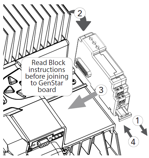
Figure 8. Ready Block Installation - refer to separate Block documentation for complete instructions
The GenStar can accommodate up to three (3) ReadyBlocks. Install additional ReadyBlocks in the same manner as the first ReadyBlock. Refer to the ReadyBlock manuals for wiring and communication cable installation instructions.
Use a knife to cut out the ReadyBlock Tabs for each corresponding block(s) being installed before replacing the ReadyBlock cover.
BMS BLOCK NOTES:
Only one BMS Block is supported per system. If multiple BMS blocks are present, a system alarm will trigger and a status message will indicate which of the BMS blocks is active for collecting data from a BMS-battery.
Additional Notes:
When using a BMS block, only a single battery (or a bank of parallel batteries) is supported in a net- work of host controllers.
When using a BMS block, only a single manufacturer of batteries is supported. If the battery-bank is changed to a new manufacturer, the user only needs to change the battery configuration type for the BMS block.
When using a BMS block, only a single battery model is supported. If a network of parallel batteries is employed, to work properly with the BMS block, all of the batteries must be of the same model.
2.5.8 Final Connections
Connecting the battery cables with reverse polarity will permanently damage the GenStar.
Connecting the solar array to the battery terminal will permanently damage the GenStar.
Confirm that the battery wire polarity is correct, and that the fused battery disconnect switch or breaker are in the OPEN position. Connect the system battery (-) cable to the GenStar battery (-) terminal. If the system is to be grounded at the battery, make the GEC connection at the battery (-) post also.
Confirm that the PV array wire polarity is correct, and that the fused PV disconnect switch or breaker is in the OPEN position. Connect the PV array (-) negative wire(s) to negative combiner box connection or PV(-) disconnect.
With all disconnects and system breakers OPEN/OFF, insert properly sized battery, PV and load fuses, where applicable, into the fuse holders.
Verify the correct battery and solar wiring voltage
To verify correct battery wiring voltage and polarity, test the voltage between the (+) battery side of the battery breaker or fused switch and a GenStar (-) terminal.
To verify correct solar wiring voltage and polarity, test the voltage between the array side of the PV (+) fused switch or breaker, and a GenStar (-) terminal.
2.5.9 Power-Up and Verify System Operation
Carefully observe the LEDs after each connection. The LEDs will indicate proper polarity and good connections.
The commissioning menu will appear with the first start-up from the factory or after a factory reset and the GenStar MPPT will not operate until after it is commissioned. See Section 2.6 Commissioning / Initial Configuration for details.
Power ON the controller by the battery breaker or fused disconnect switch.
Watch and verify that the Charging Status LED lights solid green, and then the three battery state-of- charge (SOC) LEDs blink in sequence (G-Y-R), confirming proper start-up. If they do not light, check the battery polarity (+/-) and battery voltage.
Next, the green, yellow or red LED will light depending on the battery state-of-charge (SOC). Confirm that one of these LEDs is on before going to the next step.
CLOSE the fused solar disconnect switch or breaker. If the solar input is connected while in sunlight, the charging LED indicator will light.
Confirm proper connection by observing the charging LED.
CLOSE the fused load disconnect switch or breaker, and turn the load ON to verify a proper connection. If the load does not turn on, it could be for various reasons:
The GenStar MPPT is in LVD (red LED on)
There is a short circuit in the load (LEDs blinking R/G - Y)
There is an overload condition (LEDs blinking R/Y - G)
The load is not connected, not working, or turned off
After all connections have been completed, observe the LEDs to make sure the controller is operating normally for system conditions.
2.5.10 To Power-down
ONLY disconnect the battery from the GenStar MPPT AFTER the solar input has been disconnected. Damage to the controller may result if the battery is removed while the GenStar MPPT is charging.
OPEN the solar disconnect switch or breaker.
TEST the voltage between the PV side and other side of the disconnect switch or breaker to ensure that ISOLATION from the solar input has been achieved.
If a load is connected, OPEN the load disconnect or breaker.
OPEN the battery circuit breaker or disconnect switch to ISOLATE the controller.