Charging is completely adjustable to accommodate a variety of battery chemistries. The GenStar MPPT system batteries will have different charging requirements based on application, mode of operation, season, usage schedules, load profile, etc. The GenStar MPPT's charging algorithms and settings have the capability to provide optimal charging, with flexibility for very specific demands. The charger also offers easy to use preset profiles that will facilitate good battery health.
4.2.1 Four-Stage Charging Algorithm
The GenStar MPPT offers a 4-stage battery charging algorithm for rapid, efficient, and safe battery charging. Figure 13, below, shows the sequence of stages. The first charging stage is Bulk followed by Absorption or Equalize, and then Float. Note that the Equalize and Float stages are optional depending on the charging requirements of the battery.
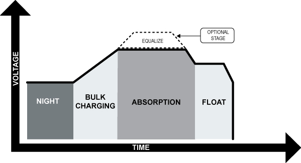
Figure 13. GenStar MPPT 4-Stage Charging Algorithm.
Bulk Charging Stage
During Bulk charging, the battery is not at 100% state of charge and battery voltage has not yet charged to the Absorption voltage set-point. The controller will deliver 100% of available solar power to recharge the battery.
Absorption Stage
When the battery has recharged to the Absorption voltage set-point, constant-voltage regulation is used to maintain battery voltage at the Absorption set-point. This prevents heating and excessive battery gassing. The battery is allowed to come to full state of charge at the Absorption voltage set-point. The green Battery SOC LED will blink once per second during Absorption charging.
The battery must remain in the Absorption charging stage for a cumulative 150-180 minutes, depending on battery type, before transition to the Float stage will occur. However, Absorption time will be extended by 30 minutes if the battery discharges below 12.50 volts (12V system) the previous night.
The Absorption set-point is temperature compensated through either the on-board local temperature sensor, or an optional Remote Temperature Sensor (RTS), if connected.
Float Stage
After the battery is fully charged in the Absorption stage, the GenStar MPPT reduces the battery voltage to the Float voltage set-point. When the battery is fully recharged, there can be no more chemical reactions and all the charging current is turned into heat and gassing. The float stage provides a very low rate of maintenance charging while reducing the heating and gassing of a fully charged battery. The purpose of float is to protect the battery from long-term overcharge. The green Battery SOC LED will blink once every two (2) seconds during Float charging.
Once in Float stage, loads can continue to draw power from the battery. In the event that the system load(s) exceed the solar charge current, the controller will no longer be able to maintain the battery at the Float set- point. Should the battery voltage remain below the Float set-point for a cumulative sixty minute period, the controller will exit Float stage and return to Bulk charging. The Float set-point is temperature compensated through the included Remote Temperature Sensor (RTS), if connected.
Equalization Stage
WARNING: RISK OF EXPLOSION
Equalizing vented batteries produces explosive gases. The battery bank must be properly ventilated.
CAUTION: EQUIPMENT DAMAGE
Equalization increases the battery voltage to levels that may damage sensitive DC loads. Verify all system loads are rated for the temperature compensated Equalize voltage before beginning an Equalization charge.
Excessive overcharging and gassing too vigorously can damage the battery plates and cause shedding of active material from the plates. An equalization that is too high or for too long can be damaging. Review the requirements for the particular battery being used in your system.
Certain batteries benefit from a periodic boost charge to stir the electrolyte, level the cell voltages, and complete the chemical reactions. Equalization (EQ) charging raises the battery voltage above the standard absorption voltage so that the electrolyte gases. The green Battery SOC LED will blink rapidly two (2) times per second during equalization charging. The duration of the equalize charge is determined by the selected battery type. See table 6 for more details. The Equalization Time is defined as time spent at the equalization set-point. If there is insufficient charge current to reach the equalization voltage, the EQ will terminate after an additional 60 minutes to avoid over gassing or heating of the battery. The GenStar MPPT meter, or LiveView, can also be used to set EQ voltage and duration.
The Equalization set-point is temperature compensated with use of the included Remote Temperature Sensor (RTS), if connected.
Why Equalize?
Routine equalization cycles are often vital to the performance and life of a battery - particularly in a solar system. During battery discharge, sulfuric acid is consumed and soft lead sulfate crystals form on the plates. If the battery remains in a partially discharged condition, the soft crystals will turn into hard crystals over time. This process, called, "lead sulfation", causes the crystals to become harder over time and more difficult to convert back to soft active materials. Sulfation from chronic undercharging of the battery is the
leading cause of battery failures in solar systems. In addition to reducing the battery capacity, sulfate build- up is the most common cause of buckling plates and cracked grids. Deep cycle batteries are particularly susceptible to lead sulfation.
Normal charging of the battery can convert the sulfate back to the soft active material if the battery is fully recharged. However, a solar battery is seldom completely recharged, so the soft lead sulfate crystals harden over a period of time. Only a long controlled overcharge, or equalization, at a higher voltage can reverse the hardening of sulfate crystals.
When to Equalize?
The ideal frequency of equalizations depends on the battery type (lead-calcium, lead-antimony, etc.), the depth of discharging, battery age, temperature, and other factors. One very broad guide is to equalize flooded batteries every 1 to 3 months or every 5 to 10 deep discharges. Some batteries, such as the L-16 group, will need more frequent equalizations.
The difference between the highest cell and lowest cell in a battery can also indicate the need for an equalization. Either the specific gravity or the cell voltage can be measured. The battery manufacturer can recommend the specific gravity or voltage values for your particular battery.
Preparation for Equalization
First, confirm that all of the system loads are rated for the equalization voltage. Disconnect any loads at risk of damage due to the high input voltage.
If Hydrocaps are used, be sure to remove them before starting an equalization. Replace the Hydrocaps with standard battery cell caps. The Hydrocaps can get very hot during an equalization. After the equalization is finished, add distilled water to each cell to replace gassing losses. Check that the battery plates are covered.
Equalize a Sealed Battery?
The GenStar MPPT Preset Charging Settings (Table 6) includes one sealed battery charging profile with an Equalization Voltage Column. This is a minimal, "boost", cycle to level individual cells. This is not a true equalization, and will not vent gas from sealed batteries that require up to 14.6V equalization charging (12V battery). The GenStar MPPT Preset Charging Settings also includes three Sealed/ Flooded battery profiles which can be used with sealed batteries that have a charging requirement of 14.5-14.8V (12V battery). However, these equalization voltage settings are intended strictly for flooded batteries only. Sealed batteries must never be equalized when using these profiles.
4.2.2 Charging Profiles
GenStar MPPT offers eight (8) preset battery charging profiles, as seen in Tables 6. These standard charging settings are suitable for lead-acid batteries ranging from sealed (gel, AGM, maintenance-free) to Flooded and Lithium cells. All voltage settings listed are for nominal 12 Volt batteries. Multiply the voltage settings by two (2) or (4), for 24 and 48 Volt systems, respectively.
NOTE:
These settings are general guidelines for use at the operator's discretion. The GenStar MPPT can also be custom programmed to satisfy a wide range of charging parameters. Consult the battery manufacturer for optimal battery charge settings.
GenStar MPPT Preset Charging Profiles (@ 25°C) | ||||||
Battery Type-Preset | Absorption Voltage | Float Voltage | Equalization Voltage | Absorption Time | Equalization Time | Equalization Timeout |
Volts | Volts | Volts | Minutes | Minutes | Minutes | |
1 - Sealed | 14.1 | 13.7 | Disabled | 150 | Disabled | Disabled |
2 - Sealed | 14.3 | 13.7 | 14.61 | 150 | 60 | 120 |
3 - Sealed / Flooded | 14.5 | 13.6 | 15.01 | 180 | 60 | 120 |
4 - Sealed / Flooded | 14.6 | 13.5 | 15.21 | 180 | 120 | 180 |
5 - Sealed / Flooded | 14.8 | 13.5 | 15.41 | 180 | 120 | 180 |
6 - LiFePO4 - Low2 | 13.6 | 13.5 | Disabled | 180 | Disabled | Disabled |
7 - LiFePO4 - Medium2 | 13.9 | 13.5 | Disabled | 20 | Disabled | Disabled |
8 - LiFePO4 High2 | 14.2 | 13.5 | Disabled | 15 | Disabled | Disabled |
Table 6. GenStar MPPT Preset Battery Charging Profiles.
CHARGING PRESET NOTES:
1 For Presets 2-5, an equalization charging stage can be initiated manually using the Start Equalization Command from the local meter or LiveView. The auto equalization interval can only be set up using custom settings.
2 LiFePO4 settings are for 4, 8 and 16-cell LiFePO4 batteries only
All settings, including charging stage voltages and timing, can be custom programmed using the local meter or LiveView. LiveView includes additional advanced custom programming options.
Do not equalize sealed batteries with preset or custom settings unless recommended by the battery manufacturer. To prevent the possibility of unintended equalization, use custom settings to disable all equalization
Settings may not be compatible with all models of these battery types.
Table 7 shows all of the high voltage disconnect and reconnect presets for each charging profile. Table 8 shows the shared settings that are common to all GenStar charging presets.
GenStar MPPT HVD-HVR Preset Charging Settings | ||
Charging Profile | Solar HVD | Solar HVR |
Battery Type-Preset | Volts | Volts |
Lead Acid Charge Presets 1-5 | Highest set-point in charging profile [+ 0.5V (@ 25ºC)]1 | 13.81 |
6 - LiFePO4 - Low | 14.2 | 13.6 |
7 - LiFePO4 - Medium | 14.4 | 13.6 |
8 - LiFePO4 High | 14.45 | 13.6 |
1 Lead Acid Solar HVD/ HVR settings are temperature compensated.
Table 7. GenStar MPPT HVD-HVR Preset Charging Settings.
Table 8 shows the shared settings that are common to all GenStar charging presets.
GenStar MPPT Shared Settings | ||
Shared Settings | Lead-Acid Value | Lithium Value |
Absorption Extension Voltage | 12.5 | Disabled |
Absorption Extension Time | Absorption Time + 30 | NA |
Float Exit Time-out Voltage | 12.6 | 13.3 |
Float Exit Time-out | 60 | 60 |
Float Cancel Voltage | 12.0 | Disabled |
Equalize Time-out | Equalize Time +60 | N/A |
Temperature Compensation Coefficient | -30 | Disabled |
Compensation Temperature Range | -20 to +40 | NA |
Low Temperature Foldback 100% | Disabled | +2 |
Low Temperature Foldback 0% | Disabled | 0 |
Table 8. GenStar MPPT Shared Preset Charging Settings.
4.2.3 Charging Variables
Each charging variable described in this section is graphically illustrated with examples below:
Absorption Extension Threshold
.jpg)
Figure 14. Absorption Extension Charging Profile.
If battery voltage discharges below the Absorption Extension Threshold the previous night, Absorption charging will be extended on the next charge cycle as shown in the example in Figure 14 above.
The voltage threshold and extension time depend on the chosen standard profile or custom settings.
Float Timeout and Float Exit Threshold
After entering the Float stage, the Float Timeout setting is applied in case the battery voltage drops due to insufficient solar charge or heavy system loads.
With Float Timeout enabled and Float Exit Threshold disabled, the Float Timeout counts the cumulative time that the battery voltage drops below the temperature compensated Float Voltage.
With both Float Timeout and Float Exit Threshold enabled, the Float Timeout will count the cumulative time that the battery voltage is less than the Float Exit Threshold Voltage.
When the Float Timeout time expires, the GenStar MPPT exits Float and begins a new Bulk / Absorption charge cycle.
Float Timeout = 60 min for all preset charging profiles
Float Exit Threshold = 12.6 for lead acid profiles (1-5)
Float Exit Threshold = 13.3 for lithium profiles (6-8)
Float Exit Time-out Voltage Threshold
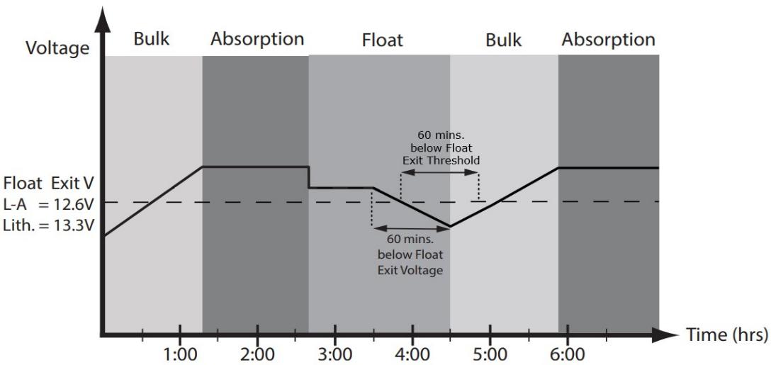
Figure 15. Float Exit Time-out Voltage Charging Profile
In Figure 15 above, the Float Timeout is set for 60 min. A system load turns on at 3:30 hours during the Float stage and runs for one hour, then turns off at 4:30 hours. During this time the load current draw is higher than the charge current so there is a net discharge causing the battery voltage to drop. If the Float Exit Threshold is disabled, the GenStar will exit Float 60 minutes after dropping out of Float and begin a new Bulk / Absorption cycle. If the Float Exit Threshold was set in this example, the battery voltage will need to drop below the Float Exit Threshold Voltage for > 60 minutes before the GenStar will drop out of Float.
The Float Exit Threshold Voltage should be set to < battery rest voltage so that the Float Timeout only counts the time that the battery is actually discharging. Longer Float Timeout and/or lower Float Exit Threshold settings will require the battery to reach a lower SOC before exiting Float.
Float Cancel Voltage
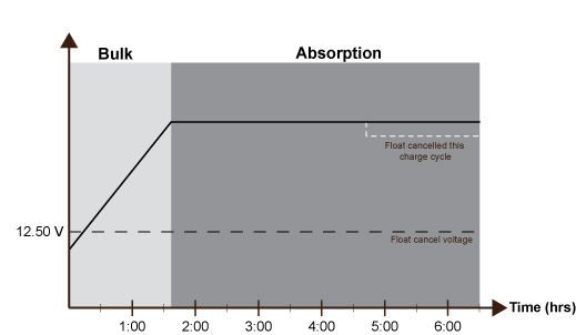
Figure 16. Float Cancel Charging Profile.
For Lead-acid presets, the battery bank discharges below 12.0 volts (24.0 volts @ 24 V) the previous night, Float charging stage will be cancelled for the next charge cycle. Figure 16 above, illustrates this concept. At 0:00 hours (dawn), battery voltage is below the Float Cancel threshold voltage. The diagram shows where Float stage would have occurred if Float was not canceled. Float cancel voltage is disabled for Lithium presets (6-8).
Equalization Time-out
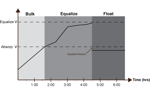
Figure 17. Equalize Time-out Charging Profile.
The charging profile in Figure 17 above, shows an Equalization Time-out event. The time-out timer begins as soon as battery voltage exceeds the Absorption voltage set-point. If there is insufficient charging current or system loads are too large, the battery voltage may not reach the Equalization set-point. Equalization Time- out is a safety feature that prevents high battery voltage for extended periods of time which may damage the battery. Equalization time-out duration depends on the chosen preset, and is also customizable.
Equalization Time-out is disabled for Lithium presets (6-8).