Refer to Figures 4 and 5.
CAUTION: RISK OF BURNS
Install the GenStar MPPT in a location that prevents casual contact. The GenStar MPPT heatsink can become very hot during operation.
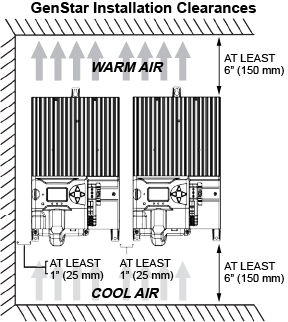
Figure 4. Required Mounting Clearance For Proper Air Flow.
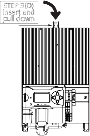
Figure 5. - Hanging GenStar Using Keyhole Slot.
Step 1: Choose mounting location
Locate the GenStar MPPT on a vertical surface that is protected from direct sun, high temperatures, and water.
Step 2: Wiring accessibility and air flow clearance
Plan and confirm wire routing access.
Verify that there is at least 6" (150 mm) of space above and below the unit, and at least 3" (75 mm) around the heatsink. See Figure 4.
Step 3: Drill holes and hang controller
Place the GenStar template on the wall where the unit will be mounted.
Mark and drill (1)-1/8" (3.175 mm) hole in the top end (slot) of the template keyhole, and two (2) lower holes for the frame holes.
Drive a #10 screw (included) into the drill hole to 1/4 in (6.35 mm) from flush with the wall.
Place the controller circular keyhole area over the wall screw, and pull the unit down to lock the screw into the slot.
Step 4: Finish securing the controller - use only panhead screws (included)
Drive the keyhole screw flush with the frame mounting hole.
Use two screws to secure the (2) unit lower frame holes flush with the wall.