WARNING: EQUIPMENT MALFUNCTION OR DAMAGE
Do not install or remove a ReadyBlock while host device is powered ON. Always power OFF the ReadyEdge device before working on ReadyBlock wiring.
N'installez pas ou ne retirez pas un ReadyBlock pendant que l'appareil hôte est sous tension. Coupez toujours l'alimentation de l'appareil ReadyEdge avant de travailler sur le câblage du ReadyBlock.
ReadyBMS
The ReadyBMS Block is wired to the battery or battery bank.
For CANBus-enabled batteries, use an 8-conductor straight-through RJ-45 cable (provided), and attach one end to one of the RJ-45 ports on the BMS Block - see Figure below. Attach the other end to a CANBus port on the BMS battery. All supported batteries conform to CAN pin configuration.
NOTE:
If the BMS Block is used with the only controller in the system, or it is at the end of a CANBus Network, the BMS Block CANBus-RJ-45 port not connected to the BMS-battery will require installation of a terminator plug (120 Ohm terminator resistor installed across the CANL and CANH wires).
A BMS Block communications terminator plug is included - see Figure 2-1 in Features Section 2.4. For any BMS-battery side CANBus termination requirement, refer to your third-party BMS-battery manufacturer’s documentation.
For parallel battery configurations, refer to the BMS-battery manufacturer’s documentation on how to connect the battery bank to the BMS Block.
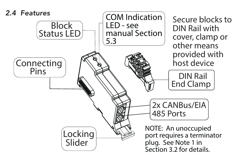
ReadyBMS Features
ReadyRelay
Disconnect all power sources to the host and all other connected devices before working with ReadyRelay wiring. Do not install or remove a ReadyRelay while the host device is powered ON.
Déconnectez toutes les sources d'alimentation de l'hôte et de tous les autres appareils connectés avant de travailler sur le câblage du ReadyRelay. N'installez pas ou ne retirez pas un ReadyRelay pendant que l'appareil hôte est sous tension.
Wire sizing and load overcurrent protection devices must conform to NEC or other jurisdictional requirements.
La taille du câblage et les dispositifs de protection contre les surintensités doivent être conformes aux exigences du NEC ou d'autres réglementations compétentes.
CAUTION: Equipment Damage
Incorrect installation or configuration may result in damage to the generator and/or other system components.
Une installation ou une configuration incorrecte peut entraîner des dommages au générateur et/ou à d'autres composants du système.
External Source Control, e.g., generator control should only be configured and installed by experienced electrical professionals.
Le contrôle de source externe, par exemple le contrôle du générateur, ne doit être configuré et installé que par des professionnels électriciens expérimentés.
Incorrect installation or configuration may result in damage to the generator and/or other system components.
Une installation ou une configuration incorrecte peut entraîner des dommages au générateur et/ou à d'autres composants du système.
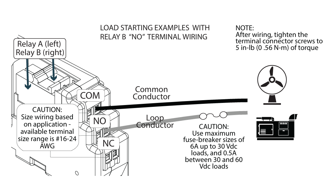
Relay contact terminals can be wired to a generator starting circuit, vent fan, communications equipment, larger relays for power switching, buzzer or trouble light (no auxiliary devices included). After wiring, tighten the terminal connector screws to 5 in-lbs. (0.56 N-m) of torque.
Automatic Generator Start-Stop (AGS)
The generator must be an electric-start model with an automatic choke. It is recommended that the generator have a two-wire start capability. Consult the generator manufacturer’s AutoStart instructions for two-wire start generators. A two-wire starting generator generally automates the cranking and starting routine. The Relay Common and Normally Open (NO) terminals can be wired to perform a two-wire generator star, as shown in the figure below.