Step 1 - Choose a proper mounting location
Locate the ReadyEdge on a surface that is protected from direct sun, high temperatures, corrosive fumes, and water. Do not install in a confined area where battery gases can accumulate.
Step 2 - Ensure sufficient spacing
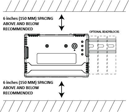
ReadyEdge Mounting Clearance
Before starting the installation, place the ReadyEdge on the surface where it will be mounted and determine where the wires will enter and exit.
NOTE: If ReadyBlock(s) will be connected to the ReadyEdge, make sure there is sufficient room to the right of the ReadyEdge for the complete assembly. The long DIN-rail 8.9 inches (225 mm) provides space for up to three (3) ReadyBlocks. The ReadyEdge can accommodate up to six ReadyBlocks. If installing more than (3) ReadyBlocks, use a section of 35mm DIN-rail that is at least 11.8 inches (300 mm) long - not included.
Verify there is sufficient space above and below the unit for entry and exit of wiring and communication cables .
Recommended Spacing
Six (6) inches / 150 mm above and below to provide sufficient wiring and cables bending room
No clearance necessary on either side. Other DIN mount devices may be mounted up against the ReadyEdge and Blocks on either side. However, it is recommended to leave one (1) inch / 25 mm on the right side to allow for ReadyBlocks removal and servicing.
These are recommended spacing requirements only. Site conditions may vary.
Step 3 - Secure the DIN rail to a mounting surface
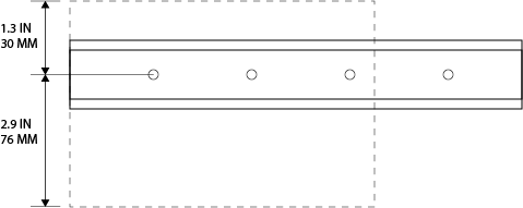
DIN-rail Mounting - ReadyEdge Body Dimensions
a. Decide which DIN-rail length will be needed for the install (included in the box). Use the shorter 75mm DIN-rail if only the ReadyEdge unit will be mounted. Use the longer 225mm DIN-rail section if ReadyBlock(s) will also be installed. Now or in the future. Alternatively, the ReadyEdge may be mounted to any standard 35mm DIN rail.
b. Reference the dimensioned diagram above to determine the exact location of the DIN-rail. Be sure the DIN-rail is level and mark the DIN-rail mounting holes on the mounting surface using a pencil or marker.
c. Check that the DIN-rail mounting screws will not penetrate wires or other objects located on the opposite side of the surface before drilling. Using a 1/8” bit, drill pilot holes for each of the mounting screws where marked.
d. Secure the DIN-rail to the mounting surface with screws appropriate for the substrate
Step 4 - Mount the ReadyEdge to the DIN-rail
Fit the Clamps around the DIN Rail as shown in the diagram
Install the Mounting Clamp Screws
Tighten screws by turning clockwise to a max torque of 2 lb-in (0.23 N-m). This centers the ReadyEdge on the DIN rail and tightens the clamps
Step 5 - Mount Optional ReadyBlock(s)
The ReadyEdge can accommodate up to six ReadyBlocks. ReadyBlocks are connected on the right side of the ReadyEdge to the DIN Rail.
Install ReadyRail accessories by fitting the ReadyBlock to the DIN Rail and sliding it to the left to securely join the ReadyRail connector to the ReadyEdge. Install additional ReadyBlocks in the same manner as the first ReadyBlock.
NOTE: Only one BMS Block may be connected to a ReadyEdge.
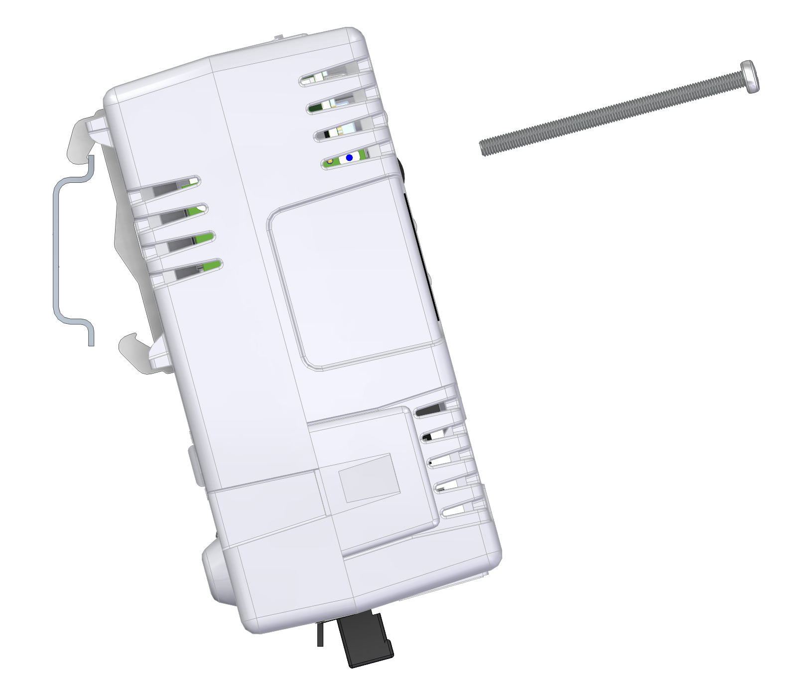
ReadyEdge Mounting Diagram